Productivity Guide
How to Reduce Cycle Time Without Creating New Automation Risk
Cycle time reduction is a common goal in automation and workholding projects. The challenge is to improve throughput without creating unstable handling, poor clamping, excessive wear or a process that operators cannot maintain.
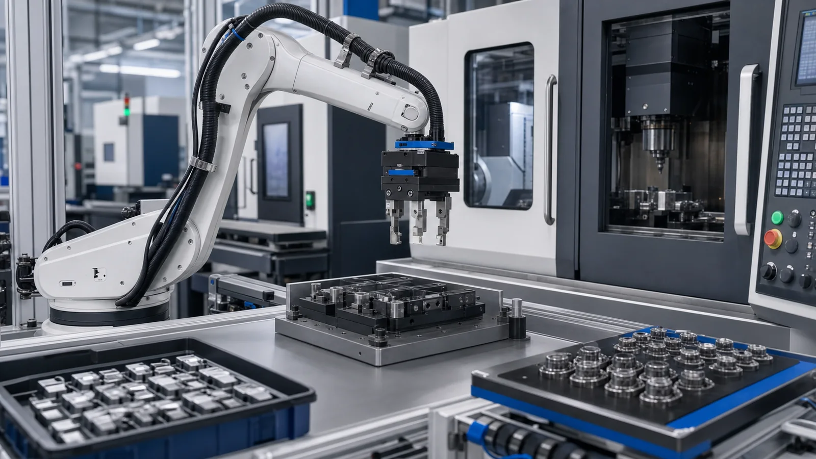
This guide explains how to analyze cycle time before selecting hardware. It does not promise a universal percentage improvement because cycle time depends on the entire production system. The goal is to help teams identify where gripping, automation and workholding decisions can make a practical difference.
1. Measure the whole process first
Start by mapping the complete sequence: part arrival, picking, transfer, placement, clamping, processing, unloading, inspection, packing and reset. Measure manual actions, machine time, robot motion, waiting time and communication delays. A visible handling movement may not be the bottleneck.
If machine cutting time dominates, a faster gripper may not change output. If operators spend time aligning parts, fixture design or zero point positioning may matter more. If the robot waits for a door or signal, control integration may be the limiting factor.
2. Separate value-added and non-value-added time
Value-added time changes the product. Non-value-added time includes waiting, searching, manual alignment, unnecessary travel, repeated setup, excess inspection caused by poor location and delayed information. Automation should target the non-value-added time that can be reduced reliably.
Not all non-value-added time is easy to remove. Some waiting may be part of safety or quality. The right target is the time that can be reduced without lowering process stability.
3. Improve part presentation
Part presentation affects how quickly and reliably a gripper or operator can pick the workpiece. Organized trays, pallets, fixture nests or conveyors may reduce searching, reorientation and failed picks. In some cases, presentation improvement provides more benefit than changing the gripper.
When discussing cycle time, provide information about how parts arrive and how they leave. If parts are randomly oriented or difficult to separate, the system may need additional sensing, mechanical guides or a different handling concept.
4. Match gripping to the real motion
A gripper must hold the part through the actual acceleration, orientation and transfer path. Choosing a smaller or faster gripper without checking stability can increase failures. Conversely, oversized gripping can add weight, reduce robot speed, increase tool length and complicate access.
Cycle time improvement should consider gripper size, jaw design, sensor feedback and tool stack-up. The goal is stable motion, not simply maximum speed.
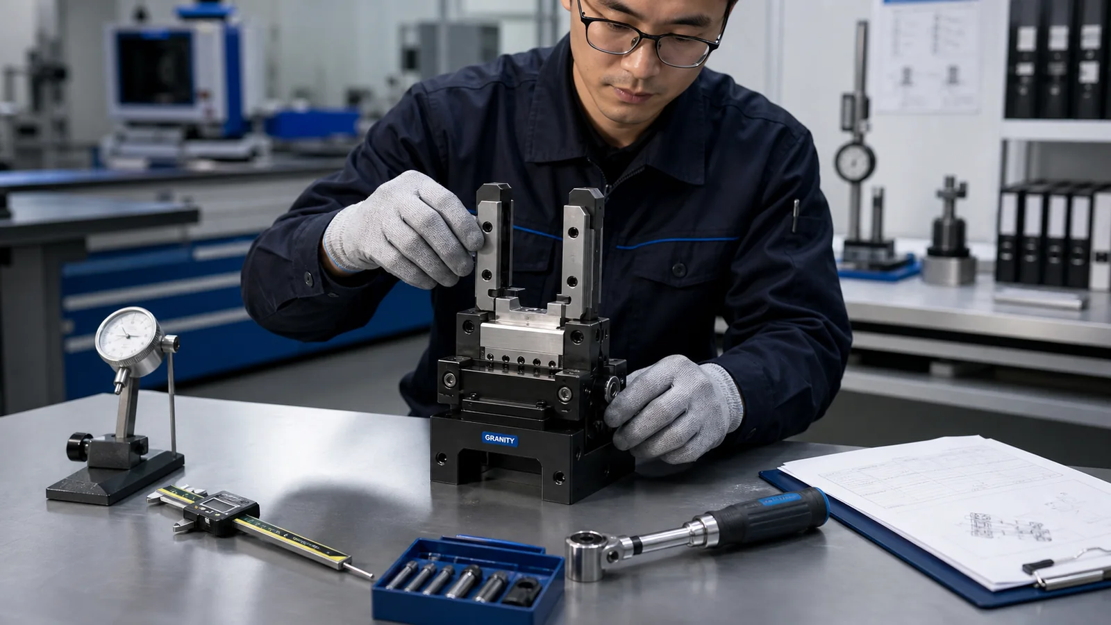
Separate machine time, handling time, setup time, waiting time and quality recovery before selecting hardware improvements.
5. Reduce fixture change and setup time
Workholding affects cycle time beyond the machine cut. Fixture setup, alignment, clamping and verification can consume significant time, especially in small-batch or high-mix production. Zero point systems, modular fixtures and standardized datum logic may reduce this time when applied correctly.
Before changing hardware, define how often fixtures change, who performs setup, what alignment steps are required and which errors occur. The best workholding improvement is usually tied to a repeatable process, not a single clamping component.
6. Review movement and access
Robot or actuator motion should be examined for unnecessary travel, poor approach angles and collision avoidance that forces long paths. However, shortening motion must not reduce safe clearance or make recovery harder. Smooth, reliable motion often beats aggressive motion that causes downtime.
Access constraints may come from machine doors, fixtures, cables, hoses, sensors or part geometry. Good layout can reduce cycle time without increasing mechanical risk.
7. Use feedback to avoid hidden delays
Part-present confirmation, jaw position feedback, fixture clamp confirmation and machine-ready signals can reduce uncertainty. Without feedback, machines may need conservative dwell time or operator intervention. With clear signals, the process can move more confidently from one step to the next.
Feedback should be designed for the actual failure modes. A sensor that confirms jaw movement may not confirm that the part is properly seated. Discuss what the system must know, not only which sensor is available.
8. Reduce information friction
Cycle time is not only physical. Engineering teams lose time when drawings, CAD, datasheets, model choices and quote information are incomplete. A structured RFQ and CAD request process can shorten the time between product interest and engineering review.
For suppliers and project teams, provide clear application details and maintain a repeatable product and asset workflow so engineers do not rebuild the same information repeatedly.
9. Cycle time inquiry checklist
Prepare the current process sequence, estimated time per step, machine type, workpiece details, handling method, fixture method, robot or actuator context, problem area, target improvement, production volume and any quality or safety constraints.
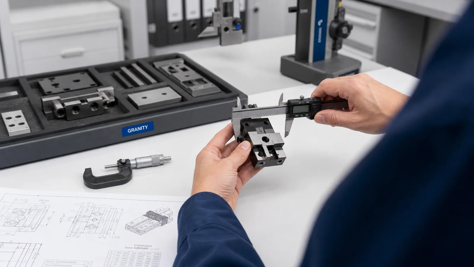
Only pursue hardware changes after the team separates true machine time, handling time, waiting time and recovery time.
10. Avoid false improvements
Do not reduce cycle time by removing checks that prevent defects. Do not increase robot speed without reviewing grip stability. Do not shorten fixture setup at the cost of repeatability. Do not treat a single successful test cycle as proof of production reliability.
Sustainable improvement comes from reducing the right time while keeping the process stable, serviceable and understandable.
11. Use product selection as a process decision
Product selection affects cycle time, but it should not be isolated from the process. A gripper may reduce handling time if it improves part capture or allows a better motion path. A tool changer may reduce manual intervention if the cell uses multiple tools. A zero point system may reduce fixture setup time if the fixture workflow is standardized.
The correct question is not “Which product is fastest?” The better question is “Which part of the process is slow, unstable or difficult to repeat, and which product family helps address that cause?” This keeps the discussion practical and prevents hardware from being used to hide a process problem.
12. CAD and engineering review for time studies
CAD can help teams estimate reach, collision risk, fixture access and tool stack length. It can also reveal when a proposed gripper or fixture position will create a longer motion than expected. For cycle time work, CAD should be used to support layout thinking and engineering review, not to claim guaranteed speed.
When requesting CAD, include the part flow, machine context and current bottleneck. If the project is about setup reduction, include the fixture or table layout. If it is about handling speed, include the robot or actuator path concept. The more specific the time problem, the more useful the CAD request becomes.
13. Build a practical improvement list
After mapping the process, classify improvements into quick changes, engineering changes and capital changes. Quick changes may include better part presentation, clearer operator steps or improved RFQ information. Engineering changes may include jaw redesign, fixture revision, sensor feedback or tool stack adjustments. Capital changes may include robot automation, tool changers, zero point systems or new workholding architecture.
This classification helps teams avoid over-investing in hardware before simpler causes have been addressed. It also helps suppliers understand whether the project is urgent purchasing, early engineering review or long-term production improvement.
14. How to turn analysis into an RFQ
Once the bottleneck and desired improvement are clear, the RFQ should state the target application, product family direction, quantity, timeline and technical constraints. It should also identify what is still open. For example, the customer may know that a zero point workholding approach is needed but still need engineering review of fixture size and machine interface.
Clear RFQ context helps GRANITY prepare a practical response. Sales can review quantity and timing, engineering can review technical gaps, and CAD or datasheet requests can stay tied to the actual productivity goal.
15. Keep improvement measurable
Every cycle-time project should define how success will be observed. The measure may be shorter setup time, fewer manual touches, more predictable part loading, reduced waiting between operations, or better machine utilization. The measure does not need to be complex, but it should be clear enough for engineering and purchasing teams to understand why the project matters.
When success is measurable, product selection becomes easier. The team can decide whether the next step is a gripping change, a tool-change concept, a workholding improvement, a CAD review or a formal RFQ. This turns a broad productivity goal into practical engineering steps and quotation requests.
Conclusion
Cycle time reduction should begin with process mapping. Once the real bottleneck is visible, teams can decide whether gripping, automation, workholding, layout, feedback or information flow should be improved first. GRANITY supports these discussions through engineering inquiry, CAD requests and RFQ support. A clear process map also helps prevent premature product selection and keeps investment tied to measurable operational improvement.
Recommended next steps
Use Technical Center resources to structure process mapping before changing hardware.
Open Technical CenterConnect cycle-time causes to gripping, automation or workholding improvements.
Browse ProductsShare process sequence, target improvement and constraints before requesting quote.
Contact EngineeringWorking on a cycle-time project?
Share the process sequence and target improvement for review.
Contact EngineeringRequest a Quote